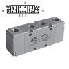
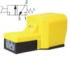
Solenoid , pneumatic and manual valves
Solenoid and pneumatic valves are used in both pneumatic and hydraulic distribution systems, most commonly in seat valve or spool configurations. It is used to control pneumatic cylinders. The valves have different functions such as 5/3, 3/2, 5/2 and can be electrically operated. The most common solenoid valves are two-way, two-position seat valves that simply open and close to allow flow when their coil is energized. However, we offer many more designs, just use the subcategories of our e-shop or read more in the advisory "How to choose the right valve".
#ShowMore#
Schematic valve markings
- each valve position is symbolized by its own square, in which the connection of inlets, outlets and outlets in that position is drawn
(i.e.: if the mark contains 2 squares, it is a 2-position valve, if it contains 3 squares, it is a 3-position valve, etc.) - the numbering or letter designation of the connections is always at the square symbolizing the basic position
- arrows connecting the connections indicate the direction of air flow, if the arrows are on both sides, the valve can be used for flow in both directions
- the air inlet and outlets are usually placed on the lower side of the square, the outlets from the valves are placed on the upper side of the square
- symbols are placed on the side of the square to indicate the method of switching between positions, with the fact that whichever square is drawn becomes active when the signal arrives (as if it had moved to the place of the square of the basic position)
Methods of switching between valve positions |
|||
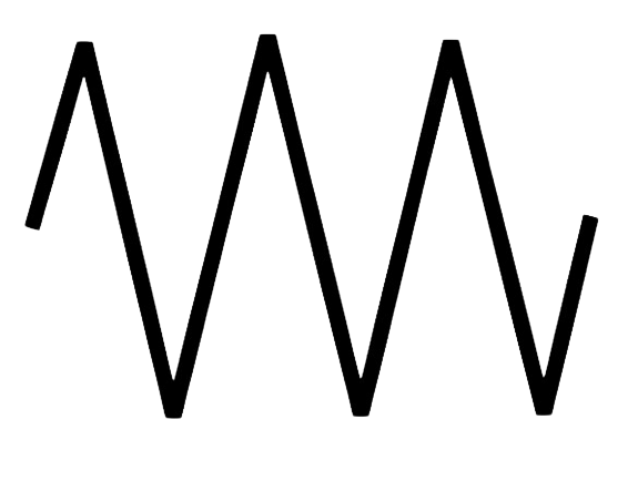 |
valve return by spring | 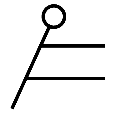 |
paw |
 |
coil, electric control | 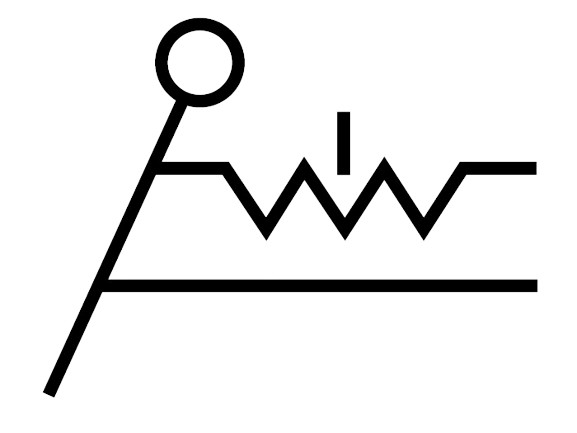 |
lever with detent |
 |
pneumatic signal | 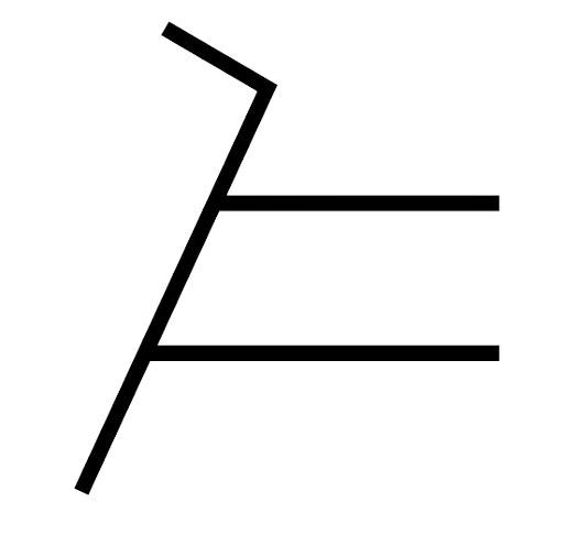 |
pedal |
 |
electromagnetic signal |  |
pedal with detent |
 |
boletus |  |
allusion |
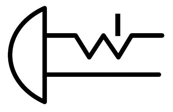 |
mushroom with arrest | 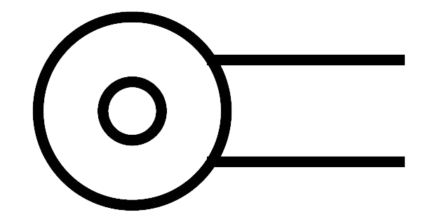 |
pulley |
 |
button | 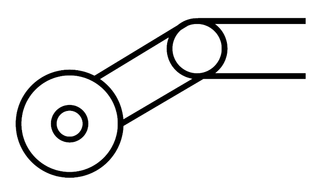 |
hinged pulley |
Examples of valve brands
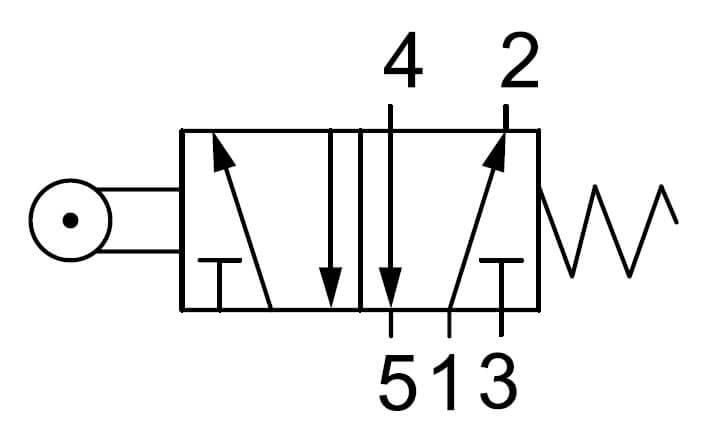 |
On this mark we see 2 squares, so it is a two position valve. The marker shows outlets 2 and 4 (top), outlets 3 and 5 and inlet 1 (bottom). There are 5 ways in total, so it is a 5/2 valve. The numerical designation of the connections is at the right square, so this is the basic position of the valve. In this ; position, air from inlet 1 goes to outlet 2, while outlet 4 is connected to exhaust 5. Exhaust 3 is closed. On the left side of the symbol is the pulley control, so it is a mechanically operated valve. When the pulley is actuated, the valve is repositioned according to the left square (adjacent to the pulley symbol). In the second position, inlet 1 is connected to outlet 4 and in turn outlet 2 is connected to vent 3, outlet 5 is now closed. By pressing the pulley, outputs 2 and 4 are therefore switched. There is a spring on the right side of the symbol, which means that the valve returns to the base position independently, using a mechanical spring. |
 |
The second example shows a two-position valve again. At the basic position we see the numerical markings 1-inlet, 2-outlet and 3-outlet. So it is a three-way valve (signals 12 and 10 are not included in the paths). In the basic position the inlet is closed and the outlet is connected to the exhaust. Signal 12 (arrow indicates air signal) from the left side moves the valve to the position according to the left square, i.e. the input is connected to output 2 (therefore the signal is marked 12 = 10 + 2). After the signal 12 has disappeared, the valve remains outside the basic position (bistable function) and stays there until the signal 10 comes from the right, which activates the basic position (10 = 10 + 0 i.e. closes the valve). You can still see the miniature button symbols on the sides. This is a representation of the so-called auxiliary manual control and the valve can be repositioned in an emergency, e.g. with a screwdriver. |
Marking of connection threads
On valve labels or schematic markings, you will often find letter or number designations for the individual connection threads. What do these markings mean? They describe whether it is an inlet, outlet, outflow or control connection. In practice, both markings are possible, but the more modern marking is by numbers.
Marking of connection threads |
||
| Number | Letter | Importance |
| 1 | P | air supply |
| 2, 4, 6 and other even numbers | A, B, C... | outputs from the valve |
| 3, 5, 7 and other odd numbers | R, S, T... | vent chambers of the valve |
| 10 + a number (10, 12, 14...) |
X, Y, Z | control signal (in the numeric marking, the second digit denotes the output that is activated by the signal e.g. 14 means that the signal lets air in at output 4, the number 10 indicates that the valve is closed ) |
Main types of valves:
- electromagnetic valves
- solenoid valves
- pneumatically operated valves
- manually operated valves
- foot valves
The most important parameters for valve selection:
- function
- threaded connection
- work pressure
- working temperature
- brightness
- flow
- power input of the coil
*Today's complex valves are not just about the open and close function. The function diagrams we add to each product photo will help you choose.
You may still find it useful when choosing automation technology:
-
 Solenoid valves; 1/8" thread up to 650 l/min
-
 Pneumatic valves 1/8"; 1/8" thread up to 650 l/min
-
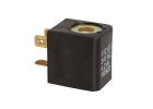 1/8" valve accessories; spools, connectors and plates
-
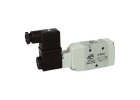 Solenoid valves; 1/4" thread up to 1,100 l/min
-
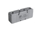 Pneumatic valves; 1/4" thread up to 1,100 l/min
-
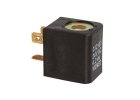 1/4" valve accessories; spools, connectors and plates
-
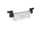 Solenoid valves; 1/2" thread up to 2,900 l/min
-
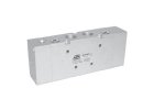 Pneumatic valves; 1/2" thread up to 2 900 l/min
-
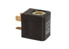 Valve accessories 1/2"; spools and connectors
-
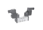 Solenoid valves; standard according to ISO 5599/1
-
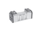 Pneumatic valves; standard according to ISO 5599/1
-
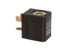 ISO valve accessories; coils, connectors and plates
-
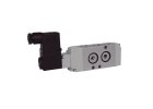 Solenoid valves; NAMUR up to 1 000 l/min
-
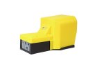 Foot valves; pedal valves
-
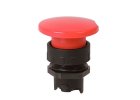 Control attachments; for base valves
-
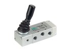 Manually operated valves; 1/4" thread up to 1,100 l/min
-
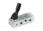 Manually operated valves; 1/4" thread up to 1,700 l/min
-
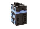 Manual base valves; for 4 mm coupling extension
Bestsellers

Connector type A12209 for ASA12 spools for A1 valves in 1/8", 1/4" and 1/2" sizes. Standard design without cable and led indication.
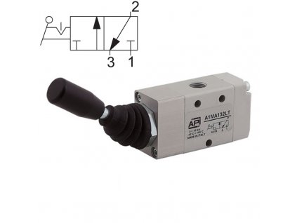
Manually operated valve - version 3/2, lever 180°, 2 positions with locking. Working pressure 0 - 10 bar, working temperature: -10 to +80 °C, materials used: body -...

Coils type ASA12 for valves A1 - 1/8", 1/4" and 1/2". Designed for 230 V AC with 4.2 VA and a response time of 10 ms. We recommend the A12209 connector as coil protection. Coils...

Manually operated valve - version 5/3, 90° lever with locking, centre position closed. Working pressure 0 - 10 bar, working temperature: -10 to +80 °C, materials used: body -...
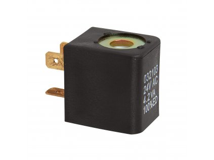
Coils type ASA12 for valves A1 - 1/8", 1/4" and 1/2". 24 V DC with 3 W power supply and 10 ms response time. We recommend the A12209 connector as coil protection. Coils are not...
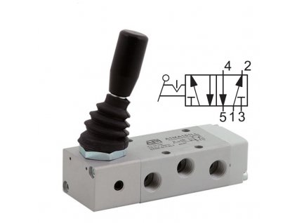
Manually operated valve - version 5/2, 90° lever with locking. Working pressure 0 - 10 bar, working temperature: -10 to +80 °C, materials used: body - aluminium/acetal resin,...

Manually operated valve - version 5/2, 180° lever with locking. Working pressure 0 - 10 bar, working temperature: -10 to +80 °C, materials used: body - aluminium/acetal resin,...

Manually operated valve - version 3/2 NC, mushroom, black without locking. Working pressure 0 - 10 bar, working temperature: -10 to +80 °C, materials used: body -...

A1E solenoid valve with 1/8" connection threads in 3/2 NC version with flow rate 650 Nl/min and DN 6,5 mm clearance. Coil ASA12 and connector A12209 are not included. For...
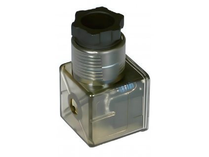
Connector type 18209 for ASA2 coils to ISO valves of size ISO1 and ISO2. Connector with LED indication, transparent, 230 V AC-DC
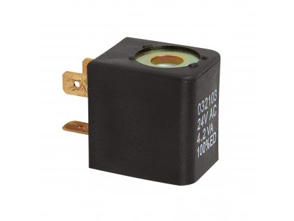
Coil type ASA12 for valves A1 - 1/8", 1/4" and 1/2". 24 V DC with 3 W power supply and 10 ms response time. We recommend the A12209 connector as coil protection. Coils are not...
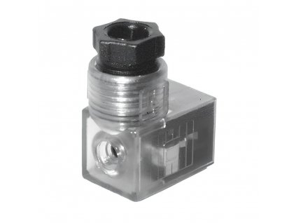
Connector type A12209 for ASA12 spools for A1 valves in 1/8", 1/4" and 1/2" sizes. Connector with LED, transparent, 230 V AC-DC.
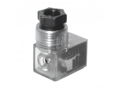
Connector type A12209T for ASA12 spools for A1 valves in 1/8", 1/4" and 1/2" sizes. Connector with LED, transparent, 24 V AC-DC.

A1E solenoid valve with 1/8" connection threads in 3/2 NO version with flow rate 650 Nl/min and DN 6,5 mm clearance. Coil ASA12 and connector A12209 are not included. For...
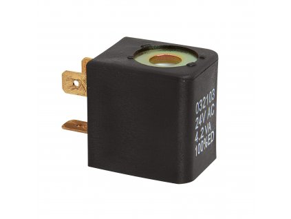
Coil type ASA12 for A1 1/8", 1/4" and 1/2" valves. 110 V AC version with 4.2 VA input and 10 ms response time. We recommend the A12209 connector as coil protection. Coils are...

Push button black as control extension - for manually operated valves with 4 mm couplings. Together with the valve it serves as a manually operated valve with miniature...

Solenoid valve A1E with 1/4" connection threads in 3/2 NC version with flow rate 1 100 Nl/min and DN 8 mm clearance. Coil ASA12 and connector A12209 are not included. For...
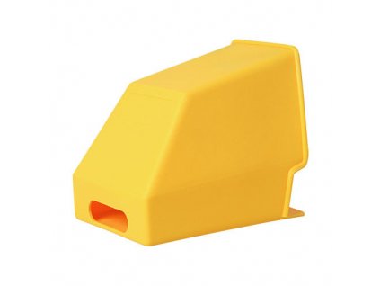
Yellow pedal guard for foot valves in 3/2 and 5/2 versions with or without locking, Materials used : plastic
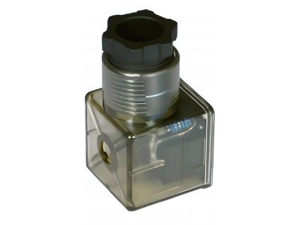
Connector type 18209 for ASA2 coils to ISO valves of size ISO1 and ISO2. Connector with LED indication, transparent, 24 V AC-DC
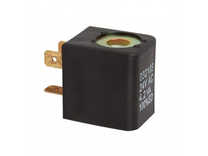
Coils type ASA12 for valves A1 - 1/8", 1/4" and 1/2". 24 V AC version with 4.2 VA and 10 ms response time. We recommend the A12209 connector as coil protection. Coils are not...

A1E solenoid valve with 1/8" connection threads in 5/2 coil/spring design with flow rate 650 Nl/min and DN 6.5 mm clearance. Coil ASA12 and connector A12209 are not included....
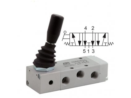
Manually operated valve - design 5/3, lever 90°, without lock, middle position vented with 1/4" threads. Working pressure 0 -10 bar, working temperature: -10 to +80 °C,...

A1E solenoid valve with 1/8" connection threads in 5/3 middle position closed with flow rate 650 Nl/min and DN 6,5 mm clearance. Coil ASA12 and connector A12209 are not...

Connector type 18209 for ASA2 coils to ISO valves of size ISO1 and ISO2. Standard design without cable and led indication.
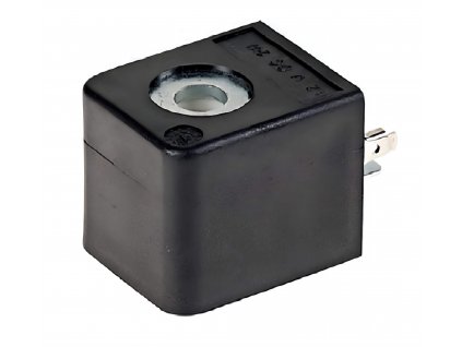
Coils type ASA2 for ISO valves size ISO1 and ISO2. 24 V AC version with 4.2 VA and 10 ms response time. We recommend the 18209 connector as coil protection. Coils are not...

Red mushroom, without locking, as control extension - for manually operated valves with 4 mm couplings. Together with the valve it serves as a manually operated valve with...

A1P pneumatic valves with 1/8" threads in 3/2 NC version with a clearance of 6.5 mm and a flow rate of 650 l/min. For stand-alone or battery mounting, use A1B1 base plates....
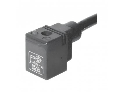
Connector type A12209 for ASA12 spools for A1 valves in 1/8", 1/4" and 1/2" sizes. Connector with LED and 2 m cable, black, 230 V AC-DC.

A1P pneumatic valves with 1/4" threads in 3/2 NC version with 8 mm clearance and flow rate of 1 100 l/min. For stand-alone or battery mounting, use A1B2 base plates. Control of...

Pedal valve - design 3/2 NC, pedal with locking. Connection via 1/4" female threads. Supplied with yellow protective cover. The clearance is 8.5 mm and the maximum air flow is...

Solenoid valve A1E with 1/8" connection threads in 3/2 NC version, auxiliary pressure supply with flow rate 650 Nl/min and DN 6,5 mm clearance. Coil ASA12 and connector A12209...
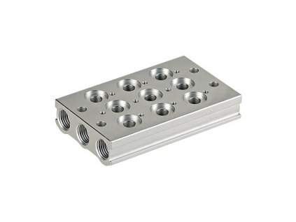
A1B2 base plate for mounting A1 valves in 1/4" size. Number of positions: 2. Side connection 3/8". Suitable for battery mounting of A1 pneumatic and electro-pneumatic valves.

Red mushroom, with locking as control extension - for manually operated valves with 4 mm couplings. Together with the valve it serves as a manually operated valve with miniature...

Lever black, 3-position as control extension - for manually operated valves with 4 mm couplings. Together with the valve it serves as a manually operated valve with miniature...

Connector type 18209 for ASA2 coils to ISO valves of size ISO1 and ISO2. Connector with LED indication and 2 m cable, black, 24 V AC-DC.

Connector type A12209 for ASA12 spools for A1 valves in 1/8", 1/4" and 1/2" sizes. Connector with LED and 2 m cable, black, 24 V AC-DC.

Solenoid valve with NAMUR connection in 3/2 NC version. Neither the ASA12 coil nor the 1A12209 connector are included. Must be purchased separately. Electrical input power 3 W...

Solenoid valve A1E with 1/2" connection threads in 5/2 coil/coil version, auxiliary pressure supply with flow rate 2 900 Nl/min and DN 15 mm clearance. Coil ASA12 and connector...

Switch black, 2-position as control extension - for manually operated valves with 4 mm couplings. Together with the valve it serves as a manually operated valve with miniature...

Pedal valve - design 3/2 NO, pedal without locking. Connection with 4 mm socket couplings. Supplied in compact dimensions. The clearance is 2.5 mm and the maximum air flow is...


