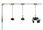
Air ducts
We have simple and very reliable systems of modular piping consisting of pipes, couplings, end boxes and the necessary mounting material, so if you are going to distribute compressed air, both in small workplaces and large halls, we recommend compressed air pipe distribution systems Push Air, SicoAir and AIRnet as the number 1 choice! At the same time, we offer you the possibility of your own design, which we will professionally arrange. If you want more information on both the systems and how to create your own design, click continue.
#ShowMore#
How to design your own compressed air distribution system ?
The right choice of material
The compressed air produced by the compressor is usually delivered to the point of consumption via piping systems. In our catalogue you will find several systems for the implementation of pipelines, of which we prefer three systems with a modern connection with socket couplings or with a tightening nut:
| Piping System |  |
 |
 |
| Area of application | small craft workshops | larger craft and maintenance workshops smaller manufacturing enterprises |
medium and large manufacturing companies |
| Outer dimensions | Ø15 to 28 mm | Ø20 to 63 mm | Ø20 to 158 mm |
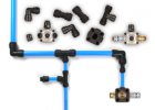
| Couplings | plug-in | with tightening nut | with tightening nut clamps with screws |
| Trumpets | grilamid PA12 aluminum |
aluminum | aluminum |
All systems are characterized by high ease of installation, low pressure gradient allowing significant savings in air production and high resistance to condensate, which is reflected in long-term trouble-free use.
Pipeline architecture
Before selecting the necessary pipes and couplings, always draw a situation plan of your operation. Record the locations where the compressor will be placed and where each workstation is located. Next, plot where you intend to run the pipeline, both the main backbone and the individual leads to the tapping points. When designing, take into account the places that the pipe will have to bypass (e.g. poles). Determine the dimensions of the hall walls and the lengths of the individual pipe sections.

When designing, you can also choose the shape of the pipe - whether it will be a straight or a loop line. Although more expensive, the loop line provides the user with
advantages in terms of the possibility of using smaller pipe sizes, even air distribution to all appliances regardless of the distance from the compressor
and also in terms of the possibility of shutting down only certain sections of the distribution system in the event of maintenance. Finally, determine the required flow rates for all abstraction points
and calculate the necessary fittings.
Pipe sizing in 10 steps
Determining the size of the pipe is a fairly complex process. The easiest way to make your work easier is to hand over the entire project to an architect or designer who will prepare a project for the customer, including all the necessary information: materials, drawings and a bill of materials. If you want to design the pipe yourself, you can use the following procedure:
- select the shape of the pipe, whether it will be straight or circular
- determine the length of the backbone main line from the compressor to the furthest point
- determine the flow rate through the pipeline according to the compressor performance
- determine the maximum air consumption of one sampling point for sizing the backbone duct lead size
- determine the number of individual fittings and valves on the backbone path from the compressor to the furthest point in the pipeline
- select AirPush, SicoAir or AIRnet duct system
- select the appropriate table for the piping system and line type and enter the backbone flow rate and maximum backbone length; subtract from the table
the required pipe size - for a given pipe size, determine the so-called replacement length of the line according to the type and number of individual fittings and valves used on the backbone according to the table
in the longest route - add the replacement length to the original length of the pipeline and check the dimension is correct as instructed in step 7; if the replacement length
lengths of dimension increased, use larger dimension of both pipes and fittings - determine the dimension of the leads from the backbone to the appliances in a similar way
Tables for piping design
All flow rates in the following tables are for a pressure of 7 bar, for design at other pressures please contact us.
 |
||||
| Replacement lengths fittings |
Size (mm) | |||
| 15 | 18 | 22 | 28 | |
| Knee | 0,7 | 1,0 | 1,3 | 1,5 |
| T-piece | 0,8 | 1,0 | 1,5 | 2,0 |
| Reduction 2d -> d | 0,4 | 0,5 | 0,5 | 0,6 |
| Ball cock | 0,1 | 0,2 | 0,3 | 0,4 |
 |
||||||
| Replacement lengths fittings |
Size (mm) | |||||
| 20 | 25 | 32 | 40 | 50 | 63 | |
| Knee | 1,2 | 1,4 | 1,7 | 2 | 2,5 | 3,5 |
| T-piece | 1,4 | 1,8 | 2,1 | 2,5 | 3 | 4 |
| 0,6 | 0,7 | 0,7 | 0,8 | 1 | ||
| Ball cock | 0,3 | 0,4 | 0,5 | 0,5 | 0,6 | 0,7 |
|
|||||||||||||||||||||||||||||||||||||||||||||||
Air Push system
|
|||||||||||||
| Length | Flow rate (l/min) | ||||||||||||
| 100 | 200 | 300 | 500 | 750 | 1 000 | 1 500 | 2 000 | 3 000 | 4 000 | 6 000 | 8 000 | 10 000 | |
| 10 meters | 15 | 15 | 15 | 15 | 18 | 22 | 22 | 28 | - | - | - | - | - |
| 25 m | 15 | 15 | 18 | 22 | 22 | 28 | 28 | - | - | - | - | - | - |
| 50 m | 15 | 15 | 22 | 22 | 28 | 28 | - | - | - | - | - | - | - |
| 75 m | 15 | 18 | 22 | 22 | 28 | 28 | - | - | - | - | - | - | - |
| 100 m | 15 | 18 | 22 | 22 | 28 | 28 | - | - | - | - | - | - | - |
| 150 m | 15 | 22 | 22 | 28 | 28 | - | - | - | - | - | - | - | - |
| 200 m | 18 | 22 | 22 | 28 | - | - | - | - | - | - | - | - | - |
| 250 m | 18 | 22 | 28 | 28 | - | - | - | - | - | - | - | - | - |
| 300 m | 18 | 22 | 28 | - | - | - | - | - | - | - | - | - | - |
| 400 m | 22 | 28 | 28 | - | - | - | - | - | - | - | - | - | - |
| 500 m | 22 | 28 | - | - | - | - | - | - | - | - | - | - | - |
Air Push system
|
|||||||||||||
| Length | Flow rate (l/min) | ||||||||||||
| 100 | 200 | 300 | 500 | 750 | 1 000 | 1 500 | 2 000 | 3 000 | 4 000 | 6 000 | 8 000 | 10 000 | |
| 25 m | 15 | 15 | 15 | 18 | 22 | 22 | 28 | 28 | - | - | - | - | - |
| 50 m | 15 | 15 | 18 | 22 | 22 | 28 | 28 | - | - | - | - | - | - |
| 75 m | 15 | 15 | 18 | 22 | 22 | 28 | 28 | - | - | - | - | - | - |
| 100 m | 15 | 15 | 18 | 22 | 22 | 28 | 28 | - | - | - | - | - | - |
| 150 m | 15 | 18 | 22 | 22 | 28 | 28 | - | - | - | - | - | - | - |
| 200 m | 15 | 18 | 22 | 28 | 28 | 28 | - | - | - | - | - | - | - |
| 250 m | 15 | 22 | 22 | 28 | 28 | - | - | - | - | - | - | - | - |
| 300 m | 15 | 22 | 22 | 28 | - | - | - | - | - | - | - | - | - |
| 400 m | 18 | 22 | 28 | 28 | - | - | - | - | - | - | - | - | - |
| 500 m | 18 | 22 | 28 | - | - | - | - | - | - | - | - | - | - |
Sico Air / AirNet system
|
|||||||||||||
| Length | Flow rate (l/min) | ||||||||||||
| 100 | 200 | 300 | 500 | 750 | 1 000 | 1 500 | 2 000 | 3 000 | 4 000 | 6 000 | 8 000 | 10 000 | |
| 10 meters | 20 | 20 | 20 | 20 | 25 | 25 | 25 | 40 | 40 | 40 | 40 | 50 | 50 |
| 25 m | 20 | 20 | 20 | 25 | 25 | 40 | 40 | 40 | 40 | 40 | 50 | 63 | 63 |
| 50 m | 20 | 20 | 25 | 25 | 40 | 40 | 40 | 40 | 40 | 50 | 50 | 63 | 63 |
| 75 m | 20 | 20 | 25 | 25 | 40 | 40 | 40 | 40 | 50 | 50 | 63 | 63 | 80 |
| 100 m | 20 | 20 | 25 | 40 | 40 | 40 | 40 | 40 | 50 | 50 | 63 | 63 | 80 |
| 150 m | 20 | 25 | 25 | 40 | 40 | 40 | 40 | 50 | 50 | 50 | 63 | 63 | 80 |
| 200 m | 20 | 25 | 25 | 40 | 40 | 40 | 40 | 50 | 50 | 63 | 63 | 63 | 80 |
| 250 m | 20 | 25 | 40 | 40 | 40 | 40 | 40 | 50 | 50 | 63 | 63 | 63 | 80 |
| 300 m | 20 | 25 | 40 | 40 | 40 | 40 | 50 | 50 | 50 | 63 | 63 | 63 | 80 |
| 400 m | 25 | 40 | 40 | 40 | 40 | 40 | 50 | 50 | 63 | 63 | 63 | 63 | 80 |
| 500 m | 25 | 40 | 40 | 40 | 40 | 50 | 50 | 50 | 63 | 63 | 63 | 80 | 80 |
Sico Air / AirNet system
|
|||||||||||||
| Length | Flow rate (l/min) | ||||||||||||
| 100 | 200 | 300 | 500 | 750 | 1 000 | 1 500 | 2 000 | 3 000 | 4 000 | 6 000 | 8 000 | 10 000 | |
| 25 m | 20 | 20 | 20 | 20 | 20 | 20 | 25 | 25 | 40 | 40 | 40 | 40 | 40 |
| 50 m | 20 | 20 | 20 | 20 | 20 | 20 | 25 | 25 | 40 | 40 | 40 | 40 | 40 |
| 75 m | 20 | 20 | 20 | 20 | 25 | 25 | 25 | 40 | 40 | 40 | 40 | 40 | 40 |
| 100 m | 20 | 20 | 20 | 20 | 25 | 25 | 25 | 40 | 40 | 40 | 40 | 40 | 40 |
| 150 m | 20 | 20 | 20 | 25 | 25 | 25 | 40 | 40 | 40 | 40 | 40 | 40 | 50 |
| 200 m | 20 | 20 | 20 | 25 | 25 | 25 | 40 | 40 | 40 | 40 | 40 | 40 | 50 |
| 250 m | 20 | 20 | 20 | 25 | 40 | 40 | 40 | 40 | 40 | 40 | 40 | 50 | 50 |
| 300 m | 20 | 20 | 20 | 40 | 40 | 40 | 40 | 40 | 40 | 40 | 50 | 50 | 63 |
| 400 m | 20 | 20 | 25 | 40 | 40 | 40 | 40 | 40 | 40 | 40 | 50 | 50 | 63 |
| 500 m | 20 | 20 | 25 | 40 | 40 | 40 | 40 | 40 | 40 | 40 | 50 | 63 | 63 |
An example of a pipeline design
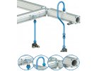
We have to design piping for a hall with a length of 150 m and a width of 100 m. The manifold pressure will be 7 bar and the compressor will deliver 3,000 l/min. The manifolds are 10 m high and a flow rate of 500 l/min is required in each of them. We will use a circuit line and we propose the AIRnet system as the pipe material, see picture.

The furthest point from the compressor station is on the far right in the picture.
The length of the line to it is:
hall length 150 m + hall width 100 m = 250 m. For the dimensioning of the backbone distribution we use the appropriate table for the circuit wiring from the AIRnet system. For length
250 m and a flow rate of 3000 l/min, subtract 40 mm.
Now determine the number and type of fittings on the route to the furthest point and calculate
according to the table for the AIRnet system AIRnet a replacement length in the assumed dimension of 40 mm:
Elbow 2 pcs × 2 m = 4 m
T-piece 8 pcs × 2.5 m = 20 m
Ball valve 3 pcs × 0,5 m = 1,5 m
The total replacement length is therefore 25.5 m + the original length of 250 m = 275.5 m.
Again, we look at the table for the dimensioning of the pipeline and even for a length of 300 m the dimension at a flow rate of 3000 l/min is still the same, i.e. the backbone line is chosen in pipes with an outer diameter of 40 mm.
Next we find the dimension of the leads, in the table for the dimensioning of the direct line in the AIRnet system we read that for a length of 10 m and the expected flow to the point of consumption
500 l/min is available in 20 mm dimension.
When is it worth thinking about compressed air distribution?
- If you need to supply compressed air to multiple appliances
- When you often work with compressed air in multiple locations in the workshop
- If automated lines are dependent on compressed air in an industrial operation
When compressed air distribution systems are pointless
- In the case of a single application
- If you own a mobile compressor for small jobs
- In a small workshop or garage where you can get by with hoses
Important information for you - A well-designed air distribution system can save you a lot of money and trouble!
Compressed air distribution systems:
- Air Push - a simple system of push-on pipes and couplings for workshops and industrial plants with pipes from 15 to 28 mm
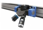
- AIRnet - a high-end connection system that can be installed by a single worker, made of lightweight aluminium tubes with outer diameters from 20 to 63 mm
- SICOAIR - extremely efficient modular system with minimal pressure gradient for compressed air distribution in craft and industry
- SICOalu2 - aesthetically perfect, modular system for craft and maintenance workshops, car and tyre workshops, laboratories
- SICO110 - modular system with large aluminium profiles for large compressed air installations
How to design a compressed air distribution system
- Start with a plan of your operation, plotting compressor locations, obstructions and take-off points
- Choose direct (lower acquisition costs) or looped (closed loop suitable for larger plants, slightly higher costs)
- Determine the maximum consumption
- Choose from the above modular systems which suits your operation best
- Determine the diameter of the pipes and fasteners
- If anything is difficult for you, please do not hesitate to let us know on +420 311 532 091 or info@kompresory-vzduchotechnika.cz, we will be happy to advise you
What else you can use when distributing air:
-
 AIR PUSH piping; 15 - 28 mm dimensions
-
.png) SICOAIR piping; with union nut 20 - 63 mm
SICOAIR piping; with union nut 20 - 63 mm
-
 AIRnet piping; 20 - 63 mm dimensions
-
 SICOALU2 piping; aluminium profiles
-
 Piping SICO110; aluminium profiles large
Bestsellers


Elbow 90° coupling with a diameter of 40 mm. Easy and fast installation, low pressure gradient, resistant to mechanical damage, UV radiation and corrosion. Operating temperature...

Powder-coated blue aluminium pipe of 40 / 36.4 mm, 6 m long, designed for piping of compressed air and inert gases up to 12.5 bar. Pipe material - AW-6060 T6 alloy.

Pipe deburrer for pipe diameter 15 - 50 mm. Operating temperature -20 °C to 70 °C. Working pressure -0.6 to 12 bar.

Manual deburring scraper for air ductwork. Easy and fast installation, low pressure gradient, resistant to mechanical damage, UV radiation and corrosion. Operating temperature...

Replacement 40 mm pipe nut for compressed air system from SicoAir compressor. Easy and fast installation, low pressure gradient, resistant to mechanical damage, UV radiation and...

Powder-coated blue aluminium pipe of 40 / 36.4 mm, 3 m long, designed for piping of compressed air and inert gases up to 12.5 bar. Pipe material - AW-6060 T6 alloy.

Ball valve with 40 mm couplings and G1 1/2" thread. Easy and fast installation, low pressure gradient, resistant to mechanical damage, UV radiation and corrosion. Operating...

Pipe cutter SICOAIR for diameter 15 - 40 mm. Easy and fast installation, low pressure gradient, resistant to mechanical damage, UV radiation and corrosion. Operating temperature...