Compressed air piping systems
We have simple and very reliable systems of modular piping consisting of pipes, couplings, end boxes and the necessary mounting material, so if you are going to distribute compressed air, both in small workplaces and large halls, we recommend compressed air pipe distribution systems Push Air, SicoAir and AIRnet as the number 1 choice! At the same time, we offer you the possibility of your own design, which we will professionally arrange. If you want more information on both the systems and how to create your own design, click continue.
#ShowMore#
Piping system design
STEP 1 - system selection
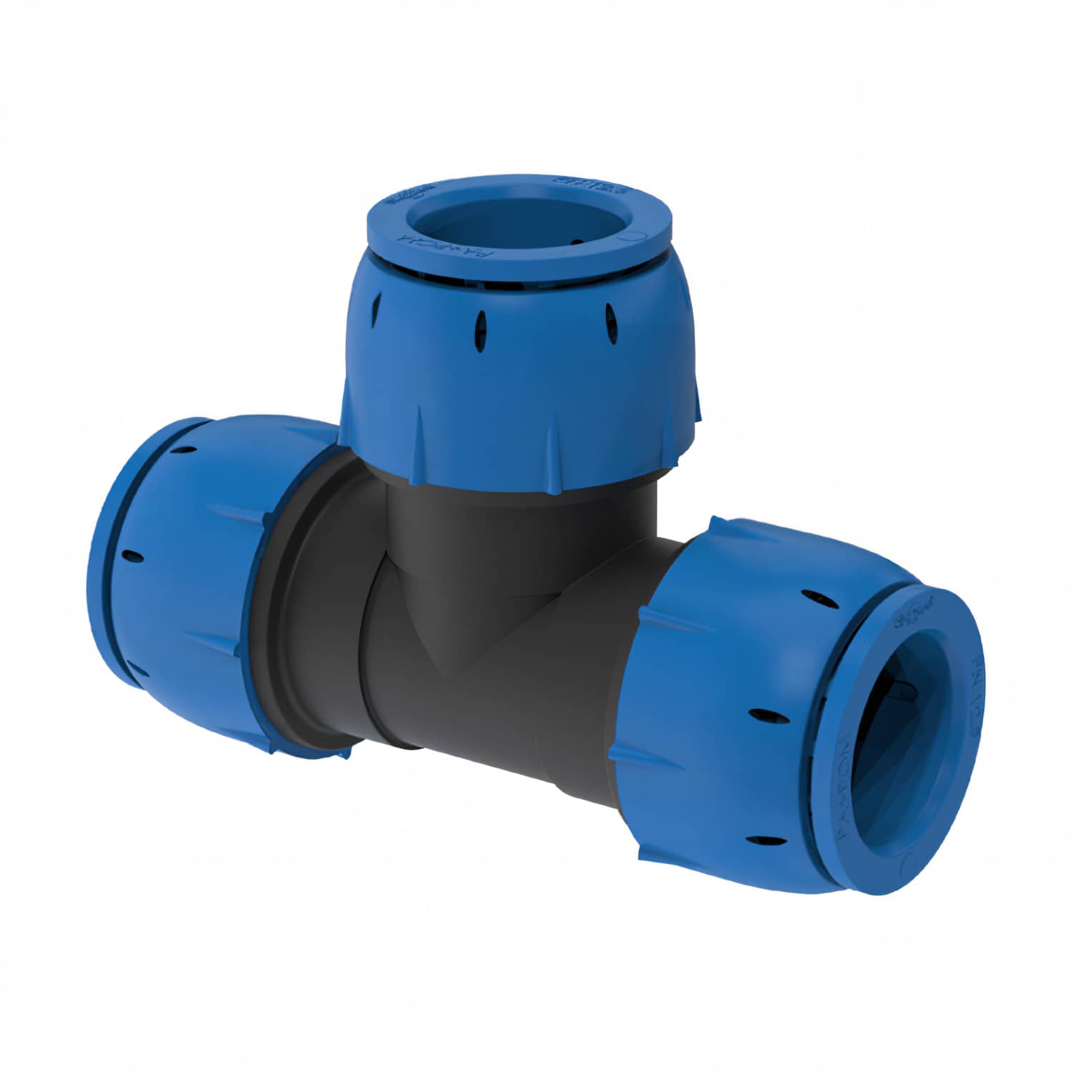
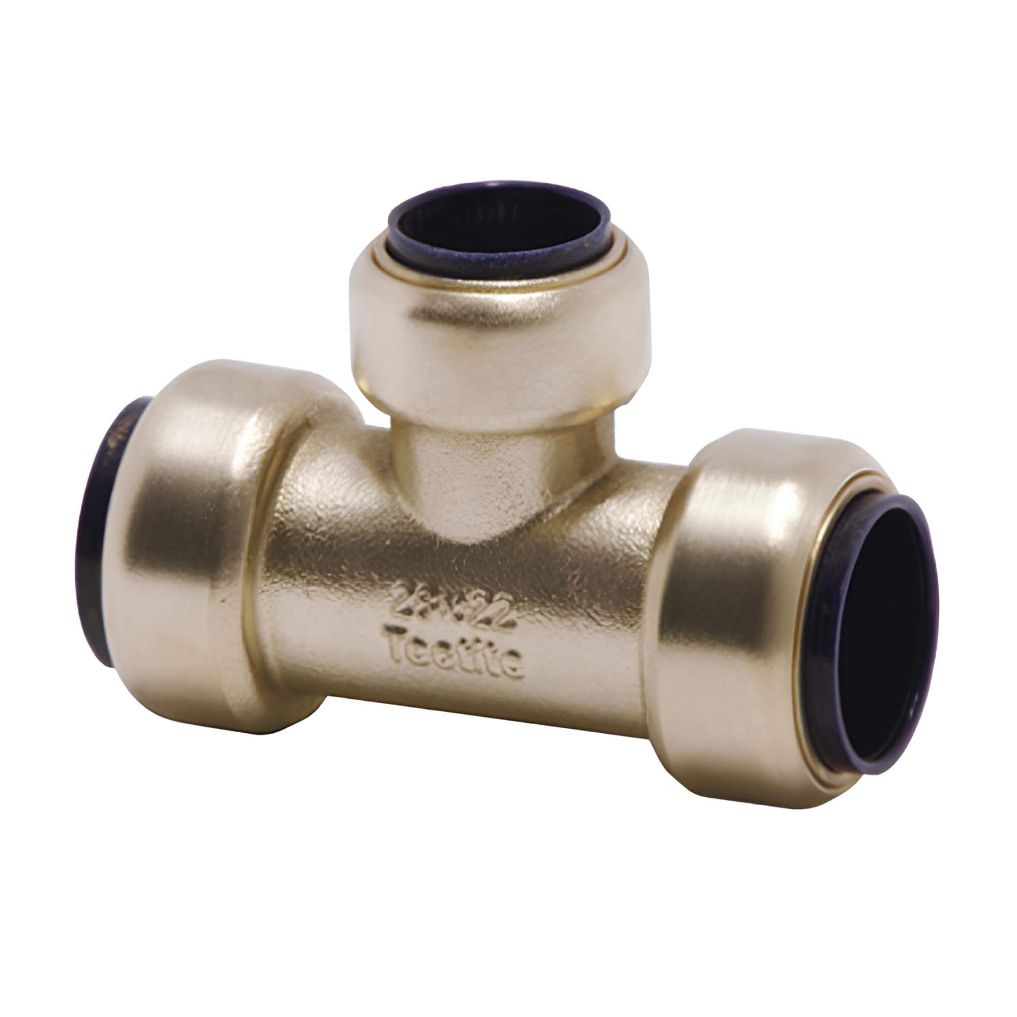
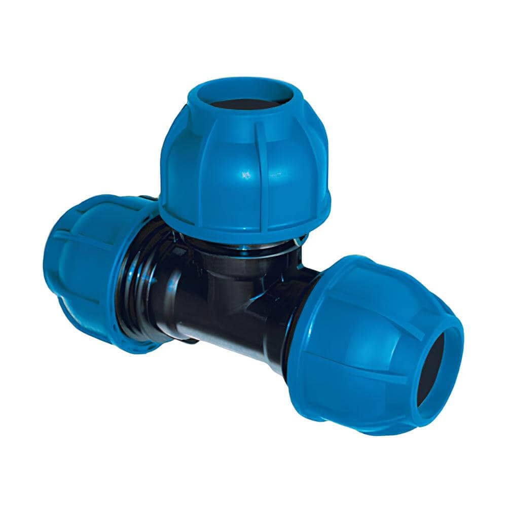
In our catalogue, you can choose from several piping systems that differ in size, connection method, choice of pipe material, working pressure and the medium for which the piping system can be used.
| Piping system | SQ | THE | Slovakia |
 |
 |
 |
|
| Diameters | 15 - 18 - 22 - 28 | 15 - 18 - 22 - 28 | Ø20 to 158 mm |
| Max. clutch pressure | 12.5 bar | 15 bar | 12.5 bar |
| Joining | plug connectors | plug connectors | screw nut |
| Trumpets | plastic, aluminum | plastic, aluminum | aluminum |
| Couplings | nylon PA6 | brass | nylon PA6 |
| Media | air | air | air, vacuum, nitrogen |
YEAR 2 - selection of pipe shape
Two concepts are used in the design of the piping architecture: direct and looped piping. The direct line is a simpler and cheaper option, where one backbone pipe runs from the compressor station to the end point. The backbone of the circuit pipe is a closed circuit, which can be additionally filled with further backbone partitions. Despite the significantly higher investment, the circuit line provides significant advantages. The length of the piping route to the furthest point is significantly reduced, which reduces the pressure gradient and allows the compressor to operate at a lower pressure and therefore at a lower energy cost. If shut-off valves are installed on the backbone, it is possible to shut off certain sections of the pipeline if rework and modifications are required.
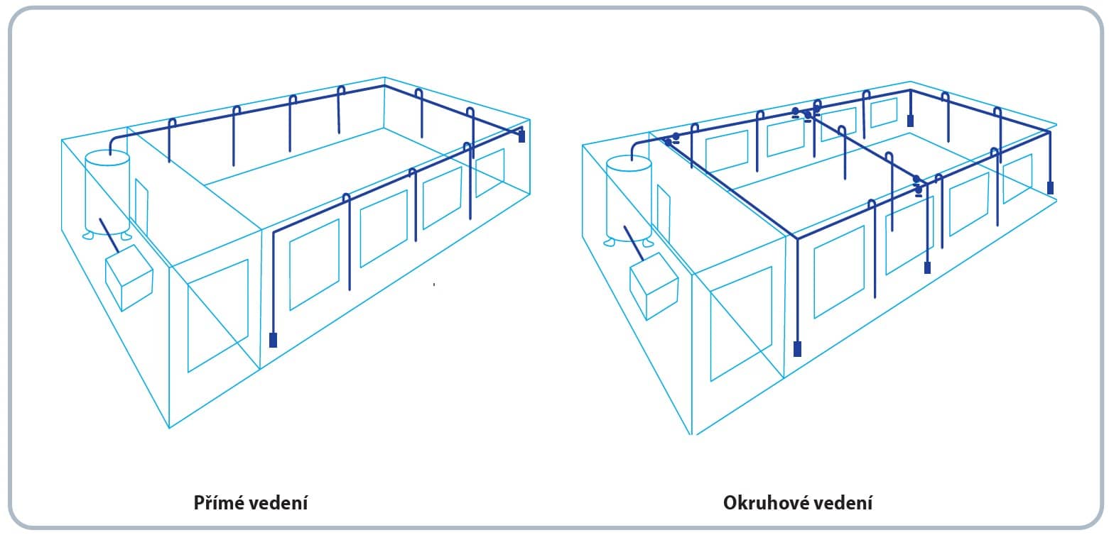
STEP 3 - Determining the pipe dimensionIn order to determine the required pipe diameter and sizing of couplings, it is useful to create a situation drawing which should include the dimensions of the hall or workshop, the route of the backbone, the individual leads and the location of the shut-off valves. Also determine the expected flow rate in the pipes. Next, plot the starting point and the furthest point to determine the longest distance of the pipeline route. In our case, this distance is 250 m. |
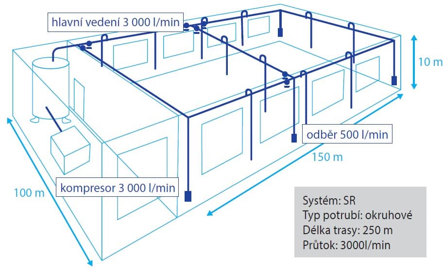 |
Once you have the necessary data, use the piping sizing table found in the introduction to each piping system. In our case, we will use the table for the SR system circuit:
Pipe sizing - SR system |
|||||||||||||
| Length | Flow rate (l/min) | ||||||||||||
| 100 | 200 | 300 | 500 | 750 | 1 000 | 1 500 | 2 000 | 3 000 | 4 000 | 6 000 | 8 000 | 10 000 | |
| 25 m | 20 | 20 | 20 | 20 | 20 | 20 | 25 | 25 | 32 | 32 | 40 | 40 | 40 |
| 50 m | 20 | 20 | 20 | 20 | 20 | 20 | 25 | 25 | 32 | 40 | 40 | 40 | 40 |
| 75 m | 20 | 20 | 20 | 20 | 25 | 25 | 25 | 32 | 32 | 40 | 40 | 40 | 40 |
| 100 m | 20 | 20 | 20 | 20 | 25 | 25 | 25 | 32 | 40 | 40 | 40 | 40 | 40 |
| 150 m | 20 | 20 | 20 | 25 | 25 | 25 | 32 | 32 | 40 | 40 | 40 | 40 | 50 |
| 200 m | 20 | 20 | 20 | 25 | 25 | 25 | 32 | 40 | 40 | 40 | 40 | 40 | 50 |
| 250 m | 20 | 20 | 20 | 25 | 32 | 32 | 32 | 40 | 40 | 40 | 40 | 50 | 50 |
| 300 m | 20 | 20 | 20 | 32 | 32 | 32 | 40 | 40 | 40 | 40 | 50 | 50 | 63 |
| 400 m | 20 | 20 | 25 | 32 | 32 | 32 | 40 | 40 | 40 | 40 | 50 | 50 | 63 |
| 500 m | 20 | 20 | 25 | 32 | 32 | 40 | 40 | 40 | 40 | 40 | 50 | 63 | 63 |
STEP 4 - Spare length of fittings
The dimension of the pipe is also influenced by the pipe's segmentation. Every bend, turn, fitting or shut-off valve puts resistance to the air flow, creates turbulence and increases the pressure gradient. After the preliminary selection of the dimension from the previous table, it is still necessary to make a correction of the selected dimension using the table and the calculation, the so-called replacement length of the fittings.
| Replacement length table fittings | ||||||||||
| Piping system | Pipe diameter (mm) | |||||||||
| 15 | 18 | 20 | 22 | 25 | 28 | 32 | 40 | 50 | 63 | |
| Knee | 0,7 | 1,0 | 1,2 | 1,3 | 1,4 | 1,5 | 1,7 | 2,0 | 2,5 | 3,5 |
| T-piece | 0,8 | 1,0 | 1,4 | 1,5 | 1,8 | 2,0 | 2,1 | 2,5 | 3,0 | 4,0 |
| Reduction 2D --> D | 0,4 | 0,5 | 0,5 | 0,5 | 0,6 | 0,6 | 0,7 | 0,7 | 0,8 | 1,0 |
| Ball cock | 0,1 | 0,2 | 0,3 | 0,3 | 0,4 | 0,4 | 0,5 | 0,5 | 0,6 | 0,7 |
| Example: | 1 × elbow | 1 × 2.0 m = 2.0 m |
| 8 × T-piece | 8 × 2.5 m = 20.0 m | |
| 4 × ball valve | 4 × 0,5 m = 2,0 m |
The total replacement length of the fittings is 24 m.
Now we re-determine the pipe dimension in step 3 for a new length of 250 + 24 = 274 m.
From the reading we can see that the pipe dimension has not changed and remains 40 mm.
IMPORTANT NOTICE !
The values shown are for compressed air, working pressure 7 bar and maximum pressure gradient 0.5 bar. For other operating conditions, please contact us and we will be happy to prepare an individual design of the piping solution.
Compressed air distribution systems:
- TA - simple system of threaded pipes and couplings for workshops and industrial plants with pipes from 15 to 28 mm
- AIRnet - a high-end connection system that can be installed by a single worker, made of lightweight aluminium tubes with outer diameters from 20 to 63 mm
- SR - extremely efficient modular system with minimal pressure gradient for compressed air distribution in craft and industry
- SICOalu2 - aesthetically perfect, modular system for craft and maintenance workshops, car and tyre workshops, laboratories
- SICO110 - modular system with large aluminium profiles for large compressed air installations
How to design a compressed air distribution system
- Start with a plan of your operation, plotting compressor locations, obstructions and take-off points
- Choose direct (lower acquisition costs) or looped (closed loop suitable for larger plants, slightly higher costs)
- Determine the maximum consumption
- Choose from the above modular systems which suits your operation best
- Determine the diameter of the pipes and fasteners
- If anything is difficult for you, please do not hesitate to let us know on +420 311 532 091 or info@kompresory-vzduchotechnika.cz, we will be happy to advise you
What else you can use when distributing air:
-
 Pipework TA; 15 - 28 mm dimensions
-
 SQ piping; 15 - 28 mm dimensions
-
.png) SICOAIR piping; with union nut 20 - 63 mm
SICOAIR piping; with union nut 20 - 63 mm
-
 AIRnet piping; 20 - 63 mm dimensions
-
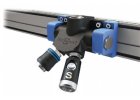 SICOALU2 piping; aluminium profiles
-
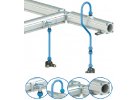 Piping SICO110; aluminium profiles large
Bestsellers

End box G1/2" x G3/8". Easy and fast installation, low pressure gradient, resistant to mechanical damage, UV radiation and corrosion. Operating temperature -20 °C to 70 °C,...

Straight socket coupling 15 mm for compressed air piping with external pipe thread G 3/8". Simple SQ socket system that can be disassembled and reused. No special tools are...

Straight socket coupling 18 mm for compressed air piping. Simple SQ socket system that can be disassembled and reused. No special tools are required for installation, which is...

Straight socket coupling 18 mm for compressed air piping. Simple SQ socket system that can be disassembled and reused. No special tools are required for installation, which is...


